Installation
Effective area, installation locations and number of antennas
In selecting the wall for installing the element, positions facing unobstructed terrain are preferred as tall and sizeable obstructions weaken the incoming mobile network signal. If possible, optimal functionality should be ensured by installing antenna elements in at least two walls in two separate directions. This guarantees broader coverage that supports multiple network operators.
It is a good idea to install the FF-SIGNAL repeater elements in open spaces where mobile devices are mostly used and through which the signals can spread evenly into the building. Installation in room corners is not recommended. Signal penetration through concrete partition walls is poor, which should be taken into account in element placement. As a general rule, a single FF-SIGNAL repeater element ensures good reception for an area of about 30–40 square metres.
- Concrete wall under a window casing/cover strip/thin coat render
- Between the frame pillars in sealed glass walls
- Between frame pillars in wooden buildings insulated with aluminium-coated panels
- Between window frames
- Between window frames and balcony doors with or without a support frame
The required number of FF-SIGNAL elements depends on the desired impact and the size of the location. Examples of recommended minimum numbers in a variety of locations are listed below:
- A small studio/one-bedroom flat, which normally consists of an open living room and kitchen, can be covered with a single FF-SIGNAL repeater element installed next to a door or window.
- For flats that reach both sides of a building, FF-SIGNAL elements are recommended on both sides of the flat.
- A floor of a large modern stone building can be covered with 3–4 elements on 2–3 sides, for example.
- For office building facades, the suitable installation interval is 3–5 metres between elements.
Installation method
In order to ensure flawless operation, FF-SIGNAL repeater elements must be installed with care and in accordance with instructions. To function properly, the element requires metal- free sections in the interior and exterior surfaces of the wall. Urethane foam must always be used to joint the edges of the FF-SIGNAL element. The interior surface and seams of the installation wall can be sealed with plastic vapour barrier tape or fabric-coated tape. However, the insulation material used in the signal repeater element itself provides an efficient vapour barrier. Do not cover the signal repeater with aluminium tape or other metals.
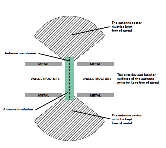
WALL STRUCTURE CROSS SECTION
The upper section of the figure represents the exterior space while
the lower section represents the room interior. The FF-SIGNAL repeater element must reach through the entire wall structure to create a pathway for the wireless signal.
FF-SIGNAL ELEMENTS MUST ALWAYS BE INSTALLED IN A VERTICAL POSITION IN THE BUILDING ENVELOPE. DO NOT COVER THE INTERIOR OR EXTERIOR SECTION OF THE ELEMENT WITH METAL.
Covering the FF-SIGNAL repeater element in an interior wall
An FF-SIGNAL element installed in an interior wall can be covered with any metal-free panel. Suitable construction panels include plasterboard, chipboard, OSB, MDF and HDF. Use of plastic vapour barriers is permitted. The interior surface of the wall can also be coated with paint that does not contain iron, carbon or graphite particles. Do not cover the FF-SIGNAL panel with aluminium-coated thermal insulation.
Covering the FF-SIGNAL repeater element in an exterior wall
The exterior portion of an FF-SIGNAL panel can be covered with any metal-free construction material that is suitable for outdoor use. Appropriate materials include wood cladding, metal-free facade panels, high-pressure laminates, plastic- based surfaces and stone-based facade materials (stoneand concrete-based facade panels must be relatively thin, 6–15 mm). Wind protection panels can also be installed on FF-signal elements.
The exterior surface of an FF-SIGNAL element can be covered with thin coat render. A nylon or fibreglass mesh must be used as the rendering mesh. Do not install a steel mesh on the FF-SIGNAL element. Do not cover the exterior surface of the FF-SIGNAL element with aluminium-plastic composite. The exterior surface of the wall can be coated with paint that does not contain iron, carbon or graphite particles.
The panel covering the exterior surface of the FF-SIGNAL element must be attached to the surrounding wall structure. If necessary, the cover panel can also be glued directly to the signal repeater element with urethane foam, urethane adhesive foam or KiiltoFlex XPU, Ardex CA 20P or Casco Aquaseal adhesive sealant.
Cutting an FF-SIGNAL repeater element
The FF-SIGNAL element can be cut into smaller sections both vertically and depthwise, but the element must always reach through the full depth of the wall structure. The element conveys the signal throughout its entire height, and the recommended minimum height is 800 mm.
Screws, nails and cutting
The optimal way of attaching an FF-SIGNAL repeater element to a wall is to glue it with urethane foam or urethane adhesive foam, so that additional penetrating screws are not required. However, a small number of penetrating screws are allowed to facilitate the fastening process.
The core section of the FF-SIGNAL element contains an antenna membrane, which can be carefully penetrated with screws and nails. However, any screws and nails through the antenna membrane should be placed no further than 100 mm from the ends of the antenna insulation. The maximum allowed number of screws penetrating the core antenna membrane is 1 screw/50 cm of spacing.
A third screw through the middle section of an unshortened signal repeater element is permitted, if this is required by the window fastening, for example. The end sections of the FF-SIGNAL element should primarily be used for any possible screw penetrations.
If the FF-SIGNAL element has been cut to a length shorter than 900 mm, the antenna membrane may be pierced with no more than two screws, both at the ends of the insulation. Shortened antenna insulations may not be penetrated by three screws.
In order to facilitate the attachment process, the FF-PIR insulation panels on both sides of the antenna membrane can be penetrated in multiple positions by various studs or screws, provided that these do not puncture the antenna membrane. The studs can help align the FF-SIGNAL element in relation to a support frame or a wooden frame pillar before the application of urethane foam. As an example, 35 x 1.7 mm wire nails with or without countersunk heads are suitable for this purpose. These types of nails or screws that do not penetrate the antenna membrane can also be used in the bottom section of the window installation frame, in which case the FF-SIGNAL element can be pressed into the nails before the application of urethane foam.
Cost efficiency
The FF-SIGNAL element is a maintenance-free product that can serve reliably for decades after installation in a wall structure. This means that, considering the entire life cycle, the passive solution is extremely competitive in comparison to resolving a reception issue retroactively.
